
- SWITCH CASE ARDUINO LIGHT SENSOR SERIAL
- SWITCH CASE ARDUINO LIGHT SENSOR UPDATE
- SWITCH CASE ARDUINO LIGHT SENSOR CODE
SWITCH CASE ARDUINO LIGHT SENSOR SERIAL
Serial.begin(9600) //Here we prepare the connection points and the serial monitor

Int sound = 500 //Here we create a variable for the Hertz (hz) that the buzzer will sound. #define trigPin 7 //#define gives a name to the connection points we use.
SWITCH CASE ARDUINO LIGHT SENSOR CODE
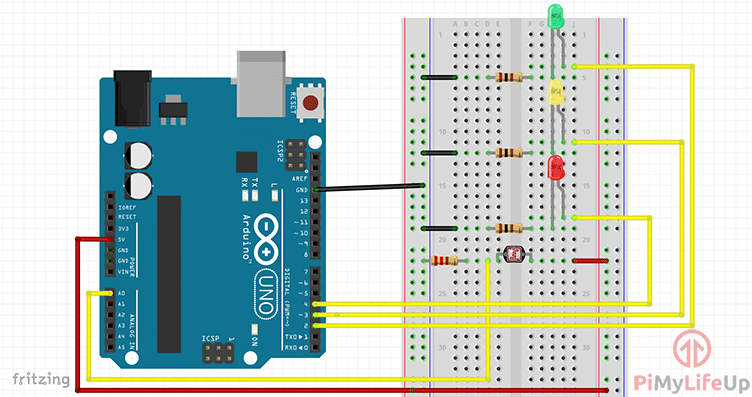
It is also important that you connect the right components to the right Arduino pins, otherwise the code will not work! Make sure you read our Arduino buying guide if you are not sure what model you need. Make sure you connect these components in the right way, otherwise your Arduino Alarm will not work! Then connect the other jumper wires according to the diagram. 1 x 10k-ohm resistor 1 x pushbutton switch 6 x 220-ohm resistors A breadboard Connecting wires Red, yellow and green LEDs Almost any Arduino will work for this project, providing it has enough pins. Arduino Board with BH1750 Ambient Light Sensor Arduino IDE. These resistors are connected in parallel on the – row of the breadboard connected. The sensor communicates with a microcontroller using I2C communication protocol. We connect the resistors to the – (the short pin) of the LEDs and buzzer. The long pin of the LEDs and buzzer is the + this can be wired directly to the Arduino pins according to the schematic.
SWITCH CASE ARDUINO LIGHT SENSOR UPDATE
You must pay attention to which pin of the LEDs and buzzer the resistor is connected to. Switch case and temperature sensor problem Using Arduino Programming Questions Mikusban September 28, 2018, 9:23pm 1 Hi, My problem is that the temperature readings wont update inside the switch case, temperature readings do update if I cycle trough the cases. So that the voltage does not become too high and blows up the components. Then the 3 LEDs and buzzer need a resistor. Serial.println(sensorReading) constants sensorMin and sensorMax.We start with wiring and placing the components on the breadboard do this according to the photo below make sure that the ultrasonic sensor is pointing in the right direction so off the breadboard off.

Print the reading from the photoresistor to the serial monitor. Here, we will discuss a project to turn ON one led from multiple LEDs based on the value in the variable. * I added the following line to the example code to calibrate the photocell in the following section*/ Blinking multiple LEDs using switch case. read the photocell and store it in the variable sensor maximum, discovered through experiment sensor minimum, discovered through experiment If the break is not placed in the code, it will continue to run through the next case, so it is very important to include the break. Once the code has ran, it will hit the break command and begin to loop through the program again. When the program gets to the switch case, it will compare the variable “range” to the 4 cases and choose which code to follow. In the example below, we have mapped “range” into numbers 0-3. It will then select the matching case, and run the code listed under it before returning to the top and looping through the code again. When using a switch case, the program will take a variable, in the example below it is “range”, and compare it to several cases. A switch case statement is used in place of multiple if statements. In this example the user will learn to use a switch case statement.


 0 kommentar(er)
